headerphoto

One of most important use of diodes based on the ability of diode to conduct current in only one direction. When the diode is mounted on an alternating current or AC current, then the sine wave is converted into unidirectional wave or DC current.

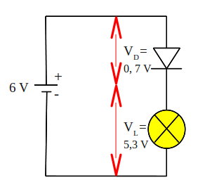
Watch what happens to the circuit below

rectifier-circuit
Electrical current is supplied to the circuit is an alternating current generated by a transformer. During the positive half cycle of AC, diodes are forward biased so current can flow. Current that flows through the diode to the load (RL) and back toward the transformer. Then the negative AC half cycle, diode does not conduct electric current, because given the reverse bias.

Waveforms of current through the load (RL) plot in the figure below.

half-wave-rectifier-circuit
A circuit that is capable of converting AC voltage into DC is called as a rectifier circuit (rectifier). While the rectifier circuit as above, producing output current from the positive half cycle of input, we call it a half-wave rectifier circuit.

Read more »»

Voltage at the positive terminal of a battery will last a constantly, until the cells ran out of charge. If we plot a graph illustrating voltage changes with time, the graph for a new battery as follows:

direct_current
Tangible graphs above is horizontal straight line. The graph shows that battery voltage will stay constant at a value of 6 V.

If we connect battery to a lamp, we can use a multimeter to measure the current flowing through it. Because the voltage is constant, thus current flow to the lamp is also constant. Current versus time graph is also a horizontal straight line, as the graph above. A flowing constant current is called as direct current, usually abbreviated to DC.

Currents that we get from some types of generators as well as electricity generators, in contrast with this DC current. Current from the generators continuously changing its direction.

Such flow is called as alternating current, abbreviated to AC. AC current is depicted graphically as shown below

alternating_current

Read more »»

To prevent damage to the LEDs due to the high voltage source, we must put in series a current limiter resistor. Resistance value appropriate to the LED current limiting resistor, can be calculated as follows.

The voltage source provided is VS (Volt). We want the LED current is I (Amperes). Assume that the LED forward voltage drop or VD to be produced is 2 V. Note the picture below

LED current limiting resistor
The voltage drop across the resistor R must be value VS - VD or equal to VS - 2. According to Ohm's Law, the value of this voltage drop should be equal to I x R, thus VS - 2 = I x R. Rearrange the equation to get the value of R will generate

VS - 2 = I x R
R = (VS - 2) / I

example question
An LED will be lit by the source voltage of 9 V and the estimated current draw of 15 mA, what is the value series resistors must be connected to the LED?

completion:
R = (VS - 2) / I
R = (9-2) V / 15 mA
R = 7 V / 0.015 A
R = 466.67 Ω
Obtained value of 466.67 Ω resistor or use a value of 470 Ω according to the reference value in the market.

Read more »»

Break down voltage or voltage drop diode is the minimum voltage on diode to electric current can flow.

A diode is not working like a resistor, that can easily a current of electricity that is charged to him. Diodes have a voltage drop, if value of applied voltage is less than the break-down voltage, the diode will not drain electrical current.

A given forward bias diode, has a voltage drop of about 0.7 V. In other words, if a given diode voltage is less than 0, 7 V, the diode will not drain the electrical current. And voltage is 0.7 V, will be a fixed voltage diode (VD) in the circuit.

breakdown-voltage-diode
Look the picture above, battery voltage source is 6 V. Voltage source will be divided in two, that is voltage drop diode (VD) and lamp voltage (VL). Known diode voltage drop is 0.7 V, then lamp voltage is equal to 6 - 0.7 = 5.3 V.

Read more »»