headerphoto

One of most important use of diodes based on the ability of diode to conduct current in only one direction. When the diode is mounted on an alternating current or AC current, then the sine wave is converted into unidirectional wave or DC current.

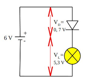
Watch what happens to the circuit below

rectifier-circuit
Electrical current is supplied to the circuit is an alternating current generated by a transformer. During the positive half cycle of AC, diodes are forward biased so current can flow. Current that flows through the diode to the load (RL) and back toward the transformer. Then the negative AC half cycle, diode does not conduct electric current, because given the reverse bias.

Waveforms of current through the load (RL) plot in the figure below.

half-wave-rectifier-circuit
A circuit that is capable of converting AC voltage into DC is called as a rectifier circuit (rectifier). While the rectifier circuit as above, producing output current from the positive half cycle of input, we call it a half-wave rectifier circuit.

Read more »»

Voltage at the positive terminal of a battery will last a constantly, until the cells ran out of charge. If we plot a graph illustrating voltage changes with time, the graph for a new battery as follows:

direct_current
Tangible graphs above is horizontal straight line. The graph shows that battery voltage will stay constant at a value of 6 V.

If we connect battery to a lamp, we can use a multimeter to measure the current flowing through it. Because the voltage is constant, thus current flow to the lamp is also constant. Current versus time graph is also a horizontal straight line, as the graph above. A flowing constant current is called as direct current, usually abbreviated to DC.

Currents that we get from some types of generators as well as electricity generators, in contrast with this DC current. Current from the generators continuously changing its direction.

Such flow is called as alternating current, abbreviated to AC. AC current is depicted graphically as shown below

alternating_current

Read more »»

To prevent damage to the LEDs due to the high voltage source, we must put in series a current limiter resistor. Resistance value appropriate to the LED current limiting resistor, can be calculated as follows.

The voltage source provided is VS (Volt). We want the LED current is I (Amperes). Assume that the LED forward voltage drop or VD to be produced is 2 V. Note the picture below

LED current limiting resistor
The voltage drop across the resistor R must be value VS - VD or equal to VS - 2. According to Ohm's Law, the value of this voltage drop should be equal to I x R, thus VS - 2 = I x R. Rearrange the equation to get the value of R will generate

VS - 2 = I x R
R = (VS - 2) / I

example question
An LED will be lit by the source voltage of 9 V and the estimated current draw of 15 mA, what is the value series resistors must be connected to the LED?

completion:
R = (VS - 2) / I
R = (9-2) V / 15 mA
R = 7 V / 0.015 A
R = 466.67 Ω
Obtained value of 466.67 Ω resistor or use a value of 470 Ω according to the reference value in the market.

Read more »»

Break down voltage or voltage drop diode is the minimum voltage on diode to electric current can flow.

A diode is not working like a resistor, that can easily a current of electricity that is charged to him. Diodes have a voltage drop, if value of applied voltage is less than the break-down voltage, the diode will not drain electrical current.

A given forward bias diode, has a voltage drop of about 0.7 V. In other words, if a given diode voltage is less than 0, 7 V, the diode will not drain the electrical current. And voltage is 0.7 V, will be a fixed voltage diode (VD) in the circuit.

breakdown-voltage-diode
Look the picture above, battery voltage source is 6 V. Voltage source will be divided in two, that is voltage drop diode (VD) and lamp voltage (VL). Known diode voltage drop is 0.7 V, then lamp voltage is equal to 6 - 0.7 = 5.3 V.

Read more »»

diode
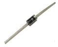
Diode is packaged in a small capsule made ​​of glass or plastic. Diode packaging has two wire terminals, one is called anode, while the other is called cathode. Usually there is a ring worn on the body diode indicating which terminal is the cathode.

A diode is generally made of silicone. Silicon is material that is not a conductor, but is not also as an insulator. Silicon is a semiconductor material. This means the characteristics of silicon is different from usual conductor materials, such as copper or iron.

A small amount of a substance mixed into the silicon to give special characteristics to the material of this diode.

Major constituent of the diode is the connection P - N or called with P - N Junction.

pn-junction
Below is symbol of diode

symbol of diode
Forward Biased and Reverse Biased Diode

forward-reverse-biased-diode
When the diode is connected as in Figure A above, where the anode wire is connected to the positive pole and the cathode connected to the negative pole of battery, we say that forward biased diode. A diode will only conduct electricity (turn on a light) when given forward bias.

When a diode is connected with reversed polarity as shown in Figure B, where the cathode wire is connected to the positive pole and the anode connected to the negative pole of battery, we say that reverse biased diode . A diode will not conduct electricity (turn off a light) when given reverse bias.

Read more »»

3-phase electrical voltage that usually denoted by R - S - T wire, when measured with a volt meter, inter-phase (RS, or RT, or ST) will show the number 380 V. But when each phase is connected with the neutral wire (RN, or SN, or TN), will show number 220 V. How could that happen?

On the power grid 380 V 3 phase, that distinguishes the phase R - S - T is phase angle, which is odds of 120 °. When we have described, it would look like this


By taking one of the blade, it would look like the following picture


We use the triangle rule, where the number of angles in a triangle is equal to 180 °, obtained angle RTN and TRN, respectively (180 ° -120 °) / 2 = 30 °


After that we use the sine rule,
380 V / sin 120 ° = RN / sin 30 °
380 V sin 30 ° = sin 120 ° RN
190 V = 0.886 RN
RN = 190 V / 0.866
RN = 220 V

That's it, voltage 3 phase 380 V can be a 1 phase 220 V, mathematics is magic.

Read more »»

220 V line voltage as in the power grid at home, which became the final stage of the electricity transmission network, a type of single-phase electricity, which uses two wires with a single phase wire (stun) and one neutral wire.

To distinguish between wire where the wire stun and neutral (non-stun), we can use a tespen. Tespen touch in the these two wires, when tespen lit, indicating wire stun, and when not lit, indicating the neutral wire.
Be careful with the wire stun, because it will give the effect of shock when a member of our body that intentionally or unintentionally touch it.

Actually this single phase electricity, derived from the three-phase power grid, which is denoted by R - S - T wire. Wire R - S - T itself has a power supply voltage 380 V between phases, commonly used for industrial purposes, particularly for electricity motors big power.

To create a single-phase electricity, simply connect the R-phase with neutral (denoted by N), or connect S phase with N, or a connect phase of T with N. See the picture below, electricity three-phase R - S - T into main breaker 3 phase. Output main breaker into sub breaker divider to be used as single-phase electricity.

three-phase R - S - T breaker

Read more »»

A light dependent resistor or LDR, composed of a disk of semiconductor material with two electrodes on its surface. In its function, the LDR is a type of resistor whose value is affected by light.

LDR
In an environment of dark or under dim light, the disc material contain free electrons in a relatively very small amount. There are few free electrons to flow of electric charge. This means that, the material is a poor conductor for electrical current. In other words, the value of very high resistance materials.

In an environment with enough light, more electrons can escape from the atoms of this semiconductor material. There are more free electrons that can drain the electric charge. Under these circumstances, the material is of a good conductor. Low electrical resistance material. The more bright light on the material, the more electrons are available, and the lower the electrical resistance of this material.

Below is a symbol of LDR

symbol of LDR
Conclusion:
  • LDR is a type of resistor whose value is affected by light
  • In the dark, the LDR resistance is very high
  • In the light of circumstances, the LDR resistance is very low

Read more »»

Thermistor (thermal resistor) is made of semiconductor materials. This component can be made in the form of discs, bars, or grains. Thermistor grain has a diameter only a few millimeters. In some thermistor grain, grain semiconductor glass wrapped by a capsule.

NTC thermistor
Because of very small size, thermistor grain can react very quickly to temperature changes. Thermistor terminals has two legs.

Most of the thermistor has resistance whose value will become smaller with increasing temperature. Thermistor type is called a negative temperature coefficient thermistor or NTC thermistor.

There is also a thermistor having a resistance value will be further enlarged with increasing temperature. Thermistor type is called a positive temperature coefficient thermistor or PTC thermistor.

Thermistor is used in the circuits or temperature gauges that provide specific responses to temperature changes. This component can also be used in circuits that will have the disorder, or even damage, caused by temperature changes.

Below is a symbol of thermistor

symbol of thermistor
Conclusion:
  • Thermistor is a type of resistor whose value is affected by temperature
  • There are two types of thermistor, which is NTC and PTC
  • NTC Thermistor gets a smaller resistance value with increasing temperature
  • PTC Thermistor gets a greater resistance value with increasing temperature

Read more »»

Light emitting diode or better known as LEDs (LED), are electronic components that can produce light when an electric current flowing through it.

LED is described with the following symbol

 LED symbol
At the beginning LED is only made in red, but now the colors of yellow, green, blue, and orange are also available on the market. There is also an infrared LED, which produces infrared light.

the colors of led
LED generally has a dome-shaped packaging material made ​​of plastic, with a protruding edge or rim at the bottom of the dome. There are two wire terminals on the bottom, which is cathode and anode. Usually the cathode wire is shorter than the anode wire, see the picture below

anode cathode led
LED requires about 20 mA current to emit light with maximum brightness, although as small as 5 mA current can still produce visible light. An average voltage drop the LED is 1.5 V, thus the supply voltage is 2 V can turn most of LED with maximum brightness. With levels higher voltages, LEDs can be damaged and caught fire when a given forward voltage exceeds 2 V.

Read more »»

KVL (Kirchhoff's Voltage Law) reads:
In any closed circuit the amount of electromotive force and potential difference is zero, or the sum of electrical voltage in a circuit equals to the sum product of current and resistance


written by equation

Σ E = Σ (I × R)

Procedure that followed in determining the circuit equation is:

  1. Pull an arrow from negative pole (-) to positive pole (+) of the voltage source, to each battery or generator
  2. Determine the direction of current flow, and show the direction of the circuit by an arrows. If specified the wrong direction, then the calculation of current value becomes negative, it indicates that the current is flowing in the opposite direction
  3. Beside each resistance describing potential difference pointing arrow in the opposite direction of current flow that flows through the resistance
  4. Surround closed loop or circuit starting from any point and end at that point anyway
  5. Write down Kirchoff voltage equations for the loop
  6. For potential arrows and potential difference arrow in a clockwise direction, given a positive sign (+) and the opposite was given a negative sign (-)

Example question 1:
Known to the circuit as shown below, where the value of E2> E1, determine the equation given in the circuit

contoh-rangkaian-tertutup
completion:
Based on the procedure KVL, drawing the circuit becomes

arah-aliran-prosedur-kvl
Circuit equations are written with
- I R1 - E1 - I R2 - R3 + I E2 = 0
E2 - E1 = I R1 + I R2 + I R3


Example question 2:
Using an example about an image, if known value of E2 = 6 V, E1 = 4 V, R1 = 10 Ω, R2 = 8 Ω, and R3 = 12 Ω, what is the current flowing in the circuit?

completion:
From the equation obtained, we write
E2 - E1 = I R1 + I R2 + I R3
E2 - E1 = I (R1 + R2 + R3)
I = (E2 - E1) / (R1 + R2 + R3)
I = (6-4) V / (10 + 8 + 12) Ω
I = 2 / 30 A
I = 0.067 A
I = 67 mA
So we get the current flowing in the circuit by 67 mA.

Read more »»

KCL (Kirchoff's Current Law) reads:
Algebraic sum of electric currents flowing toward to a point or a branching of a circuit, equal to the current that out of the point.

Written by equation

Σ I = 0

See electric current branching scheme as in the circuit below

Kirchoff's Current Law
Currents toward to the point A marked as positive (+), the points are IA, IB and ID.
Currents out of the point A marked as negative (-), that is IC
The equation becomes:
IA + IB - IC + ID = 0
IA + IB + ID = IC

Example question:
In the circuit above, it is known that IA = 10 A, IB = 6 A, IC = 18 A. What ID current is given to the circuit?

completion:
IA + IB - IC + ID = 0
10 + 6-18 + ID = 0
ID = 18 - 16 = 2 A

Read more »»

The effective capacitance or total value (Ct) a connection two or more capacitors in series, is calculated using the equation ever wrote for parallel connection to the resistance, use the formula:

1/Ct = 1/C1 + 1/C2 + 1/C3 + · · · + 1/Cn

where:
C1, C2, C3 = capacitance of each component
Cn = capacitance of the n components

Example question:
See the picture below, how many effective capacitance is given to circuit?

series connection of capacitors
completion:
1/Ct = 1/C1 + 1/C2 + 1/C3
1/Ct = 1 / 47 + 1 / 22 + 1 / 10
1/Ct = 1724/10340
1724Ct = 10 340
Ct = 10340/1742
Ct = 6 μF

conclusion:
  1. Equation series connection of capacitors equal to parallel connection of resistance
  2. Effective capacitance or total value (Ct) a series capacitor circuit is always smaller than the smallest value of capacitor in the circuit.

Read more »»

Connecting two or more capacitors in parallel can be equated by summing the plate area of each capacitor. For this reason, the effective capacitance or total value (Ct) a parallel circuit of capacitor is equal to the sum capacitance of all capacitors in the circuit. Equation parallel connection of capacitors is equal to ever wrote for series connection to the resistance, can use the formula:

Ct = C1 + C2 + C3 + · · · + Cn

where:
C1, C2, C3 = capacitance of each component
Cn = capacitance of the n components

Example question:

parallel_connection_of_capacitors
In the picture above, how many effective capacitance is given to circuit?

completion:
Ct = C1 + C2 + C3
Ct = 47 μF + 10 μF + 2.2 μF = 59.2 μF

Conclusion:

  1. Equation parallel connection of capacitors equal to series connection of resistance
  2. Effective capacitance or total value (Ct) a parallel capacitor circuit is always greater than the largest value of capacitor in the circuit.

Read more »»

Capacitance value is often printed on the capacitor body, because there is not enough space on bodies of small-sized capacitors, the capacitance values ​​must be encoded.

value_of_capacitance_of_capacitors
Code that is used consists of three digits. The first two digits of code of is the first two digits of the value of the capacitor is concerned, in units pikofarad (pF). The third digit represents the number of zeros contained in the back of two digits earlier.

Example question 1:
What is the value of capacitance of capacitors shown in the picture above?

completion:
The capacitor has a code 104, meaning that 10 followed by 4 pieces of zeros behind it. By using the value conversion units, then
C = 100000 pF
C = 100 nF
C = 0.1 μF
Capacitor values ​​obtained in the image above is 0.1 μF

Example question 2:
How much the value of the capacitor with code 223, 122 and 471?

completion:
  1. The code 223 means that 22 followed by 3 pieces of zeros behind it. This value are 22 000 pF, equal to 22 nF
  2. The code 122 means that 12 followed by 2 pieces of zeros behind it. This value is 1200 pF, equal to 1.2 nF
  3. The code 471 means that 47 is followed by 1 piece of zero behind it. This value are 470 pF, equal to 0.47 nF

Read more »»

A capacitor consists of two sides of a metal plate with an insulating layer (partition) located between these two plates. Insulator layer that is used can be a thin plastic plate, but in some types of capacitors, this layer is air.

capacitor
Picture above shows examples of the capacitor and picture below is a symbol of the capacitor.

a_symbol_of_capacitor
If a capacitor is connected to a DC source, the electrons will gather at the plate that is connected to the negative terminal of the source. These electrons will reject electrons that exist on the opposite plate. Electrons are rejected will flow towards the positive terminal of the source.

capasitor-with-dc-source
A capacitor is connected like this to the source, will be charged immediately. Voltages between the two plates is equal to the voltage power source. When the capacitor is released from the source, the capacitor retains the charge. Due to insulator layer on the capacitor, the current can not flow through the capacitor. Capacitor will remain charged up to infinite time. For this reason, capacitors are very useful for keep electrical charge.

electrical_charge
Capacitance
The ability of a capacitor to keep electrical charge is called capacitance of capacitor, with the symbol C. Unit for capacitance is farad, which is symbolized by F. One farad is defined as the amount of electrical charge that can be saved (in units of coulombs) by unit of voltage.

Capacitance of capacitor = electrical charge / voltage

Example:
Electrical charge keep in a capacitor is 6 coulombs. Voltages between the two plates is 2 V. What is the value of capacitance?

Completion:
Capacitance of capacitor = 6 / 2 = 3 F

Capacitor values
Capacitors made ​​with a value similar to the reference values ​​for the resistor. Capacitors have a higher tolerance than the resistor, so that we do not find it necessary to create as much as 24 pieces of value within that range. Capacitance values ​​in this range are:
1,0     1,2     1,5     1,8     2,2     2,7     3,3     3,9     4,7     5,6     6,8     8,2
These values ​​are repeated again with a multiple of 10.

Read more »»

By having AVO meter, multimeter, or multi tester, we can measure the voltage and amperage. However, it is necessary to note the measurement procedure on that tool.

Measurement procedure
  1. Before you connect the meter to the circuit or the load to be measured, consider whether using a source of AC or DC?
  2. Set the selector knob on the range you want
  3. If meter has auto ranging capability, you only need to select the amount of electricity (current or voltage)
  4. If you have any doubt in determining the proper range, choose the highest range
  5. Connect the meter to the circuit, or just attach both probes at two points in the circuit, note the polarity (+ and -), black to negative, and red to positive
  6. Read the value of measurement is shown (note that you avoid parallax errors in multi tester analog) and record
  7. If meter shows the reading of a very small value, you can reduce the range of measurements until you get results that can be read, but first disconnect meter from the circuit
  8. Remove the meter from the circuit after you get a correct value readings
  9. Rotate the selector knob to the off position or turn it off

Measuring Voltage and Current Electricity

Measuring-Voltage
Measuring voltage, multimeter is connected in parallel with the voltage source circuit. Meanwhile measuring the electric current, multimeter must be connected in series with the circuit. See the picture below

scheme-Measuring-Voltage-and-Current-Electricity

Read more »»

Voltage divider circuit is also known as potential divider circuit. Input to a voltage divider circuit is Vin.

Vin voltage will drive current (I) through both resistors. Because of both resistors connected in series, then the same current will flows pass through each resistor.

Voltage-divider-circuit
Effective resistance of two series resistors are R1 + R2. Drop voltage across this combination of both resistor is a Vin, according to Ohm's Law, the current flowing is
I = Vin / (R1 + R2)
Voltage at R2 becomes
Vout = I x R2
Substituting the current (I) with the first equation
Vout = Vin x R2 / (R1 + R2)

This equation is an equation to calculate the output voltage generated by a voltage divider circuit. By selecting two resistor with resistance values suitable, we can get the value of any output voltage within the range 0 to Vin (Volt).

Read more »»

USB optical mouseLess than half a year has a netbook, optical mouse has been damaged. Damage that occurs, the red indicator light is on but the mouse cursor was quiet, the pointer does not move following the mouse movements.

I did some trouble shooting, and I found that the USB cable connector at the edge was problem.

In the cable mouse consists of four small-sized wires, which is two 5 VDC power supply cable (plus and minus) and two data cables. Because of frequent moves, one of the existing data cable is broken. To fix this, prepare the tools:

  • AVO meter or Multi Tester
  • The knife cutter
  • Solder and tin
  • Isolation

Following steps:

  1. Cut the cable at least 10 cm from the edge of the USB socket
  2. Use AVO meter or multi tester to mark the color and position of the cable (identification), as shown below

    Color cable of the USB Optical Mouse
  3. Open the USB connector cover, with a vertical cut using a cutter knife, and try cut in the middle so that the result looks neat
  4. Remove the solder cable 10 cm that had been cut at the USB socket terminal
  5. Solder mouse cable to the USB socket terminal. Note the color and position of cable, must be precise not to reverse
  6. Isolate the cover. Examples of the results as shown below

    repair USB optical mouse


Reference: Elektronikabersama

Read more »»

In a the circuit mixes, some of the resistors are connected in series while the other is connected in parallel. To calculate the value of Rt in series-parallel circuit, the first method is to find the groups of resistors are all connected in series or all of which are connected in parallel.

Draw back the circuit, by replacing each group of resistors into an equivalent resistor. Gradually, simplify the circuit to produce an Rt, or the resistance of a single end.

Example question:
What is the value of Rt, or the equivalent resistance of the circuit resistor mixture below?

the circuit mixes
Completion:
On the image above the resistance value of 56 Ω and 33 Ω are connected in parallel, then parallel connection is connected in series with 47 Ω.

Create Rt1 equivalent resistance for parallel connection resistance 56 Ω and 33 Ω, with a parallel formula
1/Rt = 1/R1 + 1/R2 + 1/R3 + · · · + 1/Rn, then
1/Rt1 = 1 / 56 + 1 / 33
1/Rt1 = 89/1848
89Rt1 = 1848
Rt1 = 1848/89
Rt1 = 20.8 Ω

Parallel connection of resistance 56 Ω and 33 Ω can be replaced with an equivalent resistance of 20.8 Ω. This simplification produces two resistance are connected in series, which is 20.8 Ω and 47 Ω.

series-parallel-circuit
Equivalent series resistance value according to the series formula
Rt = R1 + R2 + R3 + · · · + Rn, then
Rt = 20.8 + 47
Rt = 68.7 Ω

Thus obtained Rt or an equivalent resistance for 67.8 Ω

an equivalent resistance

Read more »»

Code printed on the resistors are used to replace the resistor color code. This kind of code also known as code BS1852.

The code printed is using one of the three letters below, to indicate the unit and decimal point position of the resistance value. These three letters are:
R = Ohm
K = kilo Ohm
M = Mega Ohm


See the following table

Code-printed-on-resistors-table
There is also a letter that is added at the end of the code to indicate the values ​​of tolerance, which is
G = ± 2%
J = ± 5%
K = ± 10%
L = ± 20%

Example question:
What is the resistance value of resistors are marked with code
(a) 33K, (b) 4M7, (c) 2k2, (d) 1R8J, (e) 27KK

Completion:
(a) 33 kΩ
(b) 4.7 MΩ
(c) 2.2 kΩ
(d) 1.8 Ω ± 5%
(e) 27 kΩ ± 10%

Read more »»

Electrical energy generated, generally produces a voltage of 10 kV. Before distributing electric power, a trafo or transformers in generating stations will raise the voltage to 66 kV, 132 kV, or even 400 kV. Electric power in Indonesia are distributed through the grid at this voltage level.

distribusi jaringan listrik PLN
Before delivery to the customer, local transformer will reduce the voltage (gradually) to 220 V. The final phase of the voltage transformer will be 220 ​​V for use by a group of users, can be performed by a transformer mounted on the poles.

The transformer plays a vital role in the process of distribution of power. Transformer can only work with AC power. This is one reason why the electricity supplied in the form of alternating current.

Power losses
The power loss that occurs during the transmission process can be calculated as follows. Suppose that the resistance power cord that connects the station to a house is 1 Ω. Suppose that a variety of electrical devices in that house, using a 6 kW power rating. Assume that the current is distributed with source voltage of 220 V.

First calculate the electric currents
I = P / V = 6 kW / 220 V = 6000 W / 220 V = 27.3 A

Then calculate the power loss that occurs on the cable
P = I2 x R = (27.32 A)2 x 1 Ω = 745.29 W

Percentage power loss of all power supplied to the house, becomes
745.29 W / 6000 W x 100% = 12%

Now, consider what happens when the voltage is raised to 132 kV.

At higher voltages, the magnitude of electric current is
I = P / V = 6 kW / 132 kV = 6000 W / 132000 V = 0.045 A

The power loss that occurs on the cable
P = I2 x R = (0.045 A)2 x 1 Ω = 0.002 W

Percentage power loss of all power supplied to the house, becomes
0.002 W / 6000 W x 100% = 0.00003%

The amount of power loss 132 kV transmission voltage is 0.00003% of the total power delivered to the house. So that we can ignore the losses that occur in a relatively short distance after the voltage is lowered to 220 V. This is the main reason why electric energy distributed at high voltage.

Read more »»

Cable has a very important role in its function as a conductor. We must be selective in choosing and using a cable that suits your needs. Especially for large power tools with more than ten Kilo Watt (KW) such as compressors.

Below I give a table size of cable and breaker compressor
No. KW HP CABLE SIZE CIRCUIT BREAKER
1 15 20 3 X 6 mm2 + N + E 40 A
2 18 25 3 X 10 mm2 + N + E 40 A
3 22 30 3 X 10 mm2 + N + E 50 A
4 30 40 3 X 16 mm2 + N + E 63 A
5 37 50 3 X 25 mm2 + N + E 80 A
6 45 60 3 X 25 mm2 + N + E 100 A
7 55 75 3 X 35 mm2 + N + E 125 A
8 75 100 3 X 50 mm2 + N + E 160 A
9 90 125 3 X 70 mm2 + N + E 200 A
10 110 150 3 X 95 mm2 + N + E 250 A
11 132 180 3 X 120 mm2 + N + E 250 A
12 160 220 3 X 120 mm2 + N + E 300 A
13 200 270 3 X 150 mm2 + N + E 400 A
14 250 340 3 X 150 mm2 + N + E 500 A

Note: Maximum cable length is 50 m, if more than that use a larger cable
N: Neutral
E: Earth
Ekomak Compressor
Reference: Operator's Manual, Ekomak Compressor

Read more »»

charger sony ericsson k800iBelow, I give tips on repairing damage to the Sony Ericsson k800i phone charger I've ever experienced.

The damage is emerging information: Battery Charging Problem, Stop Charging.

Analysis of cases:
After review, it turns out there is a defective component 470uF/10V elco. Physically elco is seen piled on top of or term pregnancy. This damage causes the flow of electricity to charge the cell phone becomes unstable.

elco charger Sony hamil
Typically, elco 470uF/10V difficult to obtain in the market electronics stores, as a replacement could be using elco 330uF/16V, until 1000uF/16V. But note the physical height elco, shall be entered on the lid (cashing) charger.

Prepare the following tools and materials:
  1. AVO meter
  2. Solder
  3. Fat solder (stannol)
  4. Tin solder
  5. Vacuum tin (attractors)
  6. Special screwdriver phones
  7. Pliers
  8. Elco 330uF/16V

Working steps:
  • Check the charger output voltage using the AVO meter, showed good results when the value of 5, 6 Volt.
  • Open the lid (cashing) charger and heat the solder.
  • Remove the elco 470uF/10V, replace with elco 330uF/16V.

elco charger Sony diganti

Read more »»

An AVO meter (Ampere, Volt, Ohm meter) or a multimeter can measure several different electrical quantities, usually a current, voltage, and resistance. There are two kinds of multimeter, namely analog and digital.

multitester
Both multimeter has a socket or a hole for the probe step on the test rod. Positive hole is marked with a + symbol is usually red, common hole (negative) is marked with a COM or symbol - usually black. Some multi meters have a positive second socket, which should be used to measure high voltages.

probe-multitester
Both types of meter has a rotary knob to select where the quantity to be measured. This rotary knob is often also used to select a range of measurements. On an analog meter, you must connect the negative probe to the common measurement points more negative and the red probe to the measuring point is more positive. When you connect it backwards, the needle will swing downward zero. Remove immediately the two probes because it will cause damage to the meter.

Digital meters often have features otopolaritas. With this feature, the meter will show a minus sign on the left digit readout, when both probes are connected to the measurement points in reverse.

With an analog meter, there is a reading error problem when you do not read the measurement scales in a straight line from the top. Such errors are called parallax error. To help you avoid this, the meter is equipped with a curved mirror on the scale readings. You can see the reflection or shadow of the needle gauge on this mirror. When doing readings, move your head left and to right until you get the shadow coincides with a needle gauge needle. This ensures that you are looking straight down the scale and the reading will be correct.

jarum-multitester-analog
Digital meters may also have features auto ranging. This feature allows the meter to choose the appropriate range automatically when the measurement was made.

Read more »»