headerphoto

diode
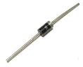
Diode is packaged in a small capsule made ​​of glass or plastic. Diode packaging has two wire terminals, one is called anode, while the other is called cathode. Usually there is a ring worn on the body diode indicating which terminal is the cathode.

A diode is generally made of silicone. Silicon is material that is not a conductor, but is not also as an insulator. Silicon is a semiconductor material. This means the characteristics of silicon is different from usual conductor materials, such as copper or iron.

A small amount of a substance mixed into the silicon to give special characteristics to the material of this diode.

Major constituent of the diode is the connection P - N or called with P - N Junction.

pn-junction
Below is symbol of diode

symbol of diode
Forward Biased and Reverse Biased Diode

forward-reverse-biased-diode
When the diode is connected as in Figure A above, where the anode wire is connected to the positive pole and the cathode connected to the negative pole of battery, we say that forward biased diode. A diode will only conduct electricity (turn on a light) when given forward bias.

When a diode is connected with reversed polarity as shown in Figure B, where the cathode wire is connected to the positive pole and the anode connected to the negative pole of battery, we say that reverse biased diode . A diode will not conduct electricity (turn off a light) when given reverse bias.

Read more »»

3-phase electrical voltage that usually denoted by R - S - T wire, when measured with a volt meter, inter-phase (RS, or RT, or ST) will show the number 380 V. But when each phase is connected with the neutral wire (RN, or SN, or TN), will show number 220 V. How could that happen?

On the power grid 380 V 3 phase, that distinguishes the phase R - S - T is phase angle, which is odds of 120 °. When we have described, it would look like this


By taking one of the blade, it would look like the following picture


We use the triangle rule, where the number of angles in a triangle is equal to 180 °, obtained angle RTN and TRN, respectively (180 ° -120 °) / 2 = 30 °


After that we use the sine rule,
380 V / sin 120 ° = RN / sin 30 °
380 V sin 30 ° = sin 120 ° RN
190 V = 0.886 RN
RN = 190 V / 0.866
RN = 220 V

That's it, voltage 3 phase 380 V can be a 1 phase 220 V, mathematics is magic.

Read more »»

220 V line voltage as in the power grid at home, which became the final stage of the electricity transmission network, a type of single-phase electricity, which uses two wires with a single phase wire (stun) and one neutral wire.

To distinguish between wire where the wire stun and neutral (non-stun), we can use a tespen. Tespen touch in the these two wires, when tespen lit, indicating wire stun, and when not lit, indicating the neutral wire.
Be careful with the wire stun, because it will give the effect of shock when a member of our body that intentionally or unintentionally touch it.

Actually this single phase electricity, derived from the three-phase power grid, which is denoted by R - S - T wire. Wire R - S - T itself has a power supply voltage 380 V between phases, commonly used for industrial purposes, particularly for electricity motors big power.

To create a single-phase electricity, simply connect the R-phase with neutral (denoted by N), or connect S phase with N, or a connect phase of T with N. See the picture below, electricity three-phase R - S - T into main breaker 3 phase. Output main breaker into sub breaker divider to be used as single-phase electricity.

three-phase R - S - T breaker

Read more »»

A light dependent resistor or LDR, composed of a disk of semiconductor material with two electrodes on its surface. In its function, the LDR is a type of resistor whose value is affected by light.

LDR
In an environment of dark or under dim light, the disc material contain free electrons in a relatively very small amount. There are few free electrons to flow of electric charge. This means that, the material is a poor conductor for electrical current. In other words, the value of very high resistance materials.

In an environment with enough light, more electrons can escape from the atoms of this semiconductor material. There are more free electrons that can drain the electric charge. Under these circumstances, the material is of a good conductor. Low electrical resistance material. The more bright light on the material, the more electrons are available, and the lower the electrical resistance of this material.

Below is a symbol of LDR

symbol of LDR
Conclusion:
  • LDR is a type of resistor whose value is affected by light
  • In the dark, the LDR resistance is very high
  • In the light of circumstances, the LDR resistance is very low

Read more »»

Thermistor (thermal resistor) is made of semiconductor materials. This component can be made in the form of discs, bars, or grains. Thermistor grain has a diameter only a few millimeters. In some thermistor grain, grain semiconductor glass wrapped by a capsule.

NTC thermistor
Because of very small size, thermistor grain can react very quickly to temperature changes. Thermistor terminals has two legs.

Most of the thermistor has resistance whose value will become smaller with increasing temperature. Thermistor type is called a negative temperature coefficient thermistor or NTC thermistor.

There is also a thermistor having a resistance value will be further enlarged with increasing temperature. Thermistor type is called a positive temperature coefficient thermistor or PTC thermistor.

Thermistor is used in the circuits or temperature gauges that provide specific responses to temperature changes. This component can also be used in circuits that will have the disorder, or even damage, caused by temperature changes.

Below is a symbol of thermistor

symbol of thermistor
Conclusion:
  • Thermistor is a type of resistor whose value is affected by temperature
  • There are two types of thermistor, which is NTC and PTC
  • NTC Thermistor gets a smaller resistance value with increasing temperature
  • PTC Thermistor gets a greater resistance value with increasing temperature

Read more »»

Light emitting diode or better known as LEDs (LED), are electronic components that can produce light when an electric current flowing through it.

LED is described with the following symbol

 LED symbol
At the beginning LED is only made in red, but now the colors of yellow, green, blue, and orange are also available on the market. There is also an infrared LED, which produces infrared light.

the colors of led
LED generally has a dome-shaped packaging material made ​​of plastic, with a protruding edge or rim at the bottom of the dome. There are two wire terminals on the bottom, which is cathode and anode. Usually the cathode wire is shorter than the anode wire, see the picture below

anode cathode led
LED requires about 20 mA current to emit light with maximum brightness, although as small as 5 mA current can still produce visible light. An average voltage drop the LED is 1.5 V, thus the supply voltage is 2 V can turn most of LED with maximum brightness. With levels higher voltages, LEDs can be damaged and caught fire when a given forward voltage exceeds 2 V.

Read more »»

KVL (Kirchhoff's Voltage Law) reads:
In any closed circuit the amount of electromotive force and potential difference is zero, or the sum of electrical voltage in a circuit equals to the sum product of current and resistance


written by equation

Σ E = Σ (I × R)

Procedure that followed in determining the circuit equation is:

  1. Pull an arrow from negative pole (-) to positive pole (+) of the voltage source, to each battery or generator
  2. Determine the direction of current flow, and show the direction of the circuit by an arrows. If specified the wrong direction, then the calculation of current value becomes negative, it indicates that the current is flowing in the opposite direction
  3. Beside each resistance describing potential difference pointing arrow in the opposite direction of current flow that flows through the resistance
  4. Surround closed loop or circuit starting from any point and end at that point anyway
  5. Write down Kirchoff voltage equations for the loop
  6. For potential arrows and potential difference arrow in a clockwise direction, given a positive sign (+) and the opposite was given a negative sign (-)

Example question 1:
Known to the circuit as shown below, where the value of E2> E1, determine the equation given in the circuit

contoh-rangkaian-tertutup
completion:
Based on the procedure KVL, drawing the circuit becomes

arah-aliran-prosedur-kvl
Circuit equations are written with
- I R1 - E1 - I R2 - R3 + I E2 = 0
E2 - E1 = I R1 + I R2 + I R3


Example question 2:
Using an example about an image, if known value of E2 = 6 V, E1 = 4 V, R1 = 10 Ω, R2 = 8 Ω, and R3 = 12 Ω, what is the current flowing in the circuit?

completion:
From the equation obtained, we write
E2 - E1 = I R1 + I R2 + I R3
E2 - E1 = I (R1 + R2 + R3)
I = (E2 - E1) / (R1 + R2 + R3)
I = (6-4) V / (10 + 8 + 12) Ω
I = 2 / 30 A
I = 0.067 A
I = 67 mA
So we get the current flowing in the circuit by 67 mA.

Read more »»